Category: website

Rendering transparency and black on HoloLens

HoloLens is an additive display. It can only add light to the real world and not block light to make the world look darker. This means that if you show an image with a black and white gradient the black part will be transparent and the white part will be opaque. Alpha (transparency) does not matter for blending with the real world. However alpha does play a role when blending with other 3D content that is rendered behind the image.

When recording a photo or video the on-board colour camera is used to capture the outside world. This is blended with the rendered scene and this typically results in a different result than what the user actually sees on the device.

The all encompassing alpha blending experiment

First I created 4 textures to show on a quad. All textures have an alpha of 1 (opaque) in the center and 0 (fully transparent) on the outside. The differences are in the RGB colors of these textures:

  • white center to white outside
  • white center to black outside
  • black center to white outside
  • black center to black outside

The images I used on a blue background for contrast:

This image has an empty alt attribute; its file name is whitefade.pngThis image has an empty alt attribute; its file name is whiteblackfade.pngThis image has an empty alt attribute; its file name is blackwhitefade.pngThis image has an empty alt attribute; its file name is blackfade.png
Images as used in the columns

Unity scene

I setup a simple test scene with a number of quads with these different textures and blend modes. The rows in this scene show the common shader blend modes. The stretched box behind each row is there to show the difference between blending the real world (where the dark gray background is in Unity).

Here’s what it looks like in Unity:

The common shader blend modes that I keep needing to lookup:

Blend SrcAlpha OneMinusSrcAlpha // Traditional transparency
Blend One OneMinusSrcAlpha // Premultiplied transparency
Blend One One // Additive
Blend OneMinusDstColor One // Soft additive
Blend DstColor Zero // Multiplicative
Blend DstColor SrcColor // 2x multiplicative

In HoloLens simulation

Rendering this scene on HoloLens will make all black parts invisible because light can only be added. It’s almost impossible to capture this with a camera through the actual device. So I created a composition to show a simulation of what it looks like in the HoloLens. Basically an additive blend with the background image.

HoloLens PhotoVideo camera capture

The HoloLens has a colour camera in the middle above the eyes to capture photos and videos. The resulting photos and videos are a composition of what the colour camera captured and a image of the rendered scene. It’s important to know that this composition uses the alpha value that is rendered in the scene instead of doing an additive blend like I did in the composition above. This will make the outcome a bit different in some cases.

Here’s what it looks like when this scene is captured on HoloLens:

However this is not what the user sees. When you look at the fourth column you can clearly see a few parts where there is black shown on top of the real world. That is impossible on the actual device (as seen in the simulation).

Another noticeable difference is that between the white image with traditional transparency and the white to black image with premultiplied transparency blending. In Unity and on HoloLens these images look similar, but on the captured image they look different. There’s a black halo around the image. This tells me that for HoloLens capture purposes it is better to use traditional transparency.

Black halo in capture

Rendering black: a matter of perception

Although technically an additive light display cannot render black it is possible to perceive darkening. When a dark part is rendered in front of a lighter area the user will perceive this as a darker colour. In practice this is highly dependent on the brightness of the HoloLens display, the brightness of the environment and the amount of lighter surroundings in the 3D scene.

When you look at the top right quads in the photos above you see that the simulation (left) shows the background and the captured image (right) shows a black colour on top of the background bar. In practice the perceived effect will be a mix of these two images.

HoloLens Simulation vs HoloLens camera capture

This effect of visual perception is demonstrated in this well known Checker shadow illusion by Edward Adelson. Tiles A and B in this image have the exact same colour, but the perceived colours differ because of it’s surrounding.

On HoloLens this can be used to create parts that are perceived as almost black by surrounding it with a lighter area. For instance black text with a light background plane will be visible, but a black text alone will not. This will work best if you use it in a dimmed environment and when the brightness of the HoloLens is set to its highest.

More

Blowing bubbles with Shader Graph

I ran into a two weekly Techart challenge by Harry Alisavakis with the theme Watercolors. I decided to participate and use Shader Graph in Unity for doing some soap bubble rendering.

Reflections & Iridescence

Real life soap bubble

The most visible features of a soap bubble are its reflections and its rainbow like colours. You can see reflections from both the front and back side of the bubble surface. This results in a mirrored reflection of the environment of the bubble.

The colours are caused by interference of the light that is reflected from the outside and the inside of the thin bubble surface. This phenomenon is called iridescence and it can also be found in sea shells, butterflies, insects, but you may also know it from the surface of a CD. When you inspect the bubble surface closely you can see a complex pattern of dancing colours. This is caused by variations in the bubble surface thickness due to complex fluid interactions that are known as the Marangoni effect.

Reflections in Shader Graph

For the reflections I created a simple room with with two fake windows. A reflection probe was used to bake it into a cubemap. Alternatively you could also use a HDRI image captured in real-life.

Bubbles need windows to reflect

A basic PBR graph with the Workflow set to Specular, Surface to Transparent and a Smoothness of 1 will already give you a nice reflective material. Add in a bit of Fresnel effect so the reflections are mostly noticeable on the outside and here’s the result.

Shaders are made easy with Shader Graph
Cubemap reflection with Fresnel falloff

Iridescence in Shader Graph

I took a more artistic approach for the simulation of the bubble surface variations by blending two layers of scrolling noise. This misses the swirls that you typically see in a real bubbles, but this won’t be noticeable at a distance. I added a vertical falloff to simulate that the thickness of a bubble is a bit larger at the bottom of the bubble. The surface thickness variations result an animated grayscale value. A gradient lookup gradient is then used to determine the iridescence colour. The gradient is based on a paper by Andrew Glassner.

The iridescence part hooks into the specular colour of the PBR node
Front face reflection and iridescence

Double sided materials

To create a double-sided material with different handling of forward and backward facing materials you can use the IsFrontFace node and branch into different parts of the shader based on the value. This works well with opaque materials and can be done in a single pass. Below you see a simple example that displays the result on an open cylinder.

Opaque material marked as a Two Sided
Two-sided opaque material ShaderGraph
Open cylinder with two-sided material applied

Double sided transparency

With transparent materials we typically want to do a separate backface pass and frontface pass to at least have a coarse way of sorting the model surfaces. That is easy to do in a ShaderLab (hand-coded) shader, but a bit harder when using Shader Graph.
Since the Universal Rendering Pipeline (URP) only supports one pass materials by default we need to come up with a different trick. We could create a copy of the mesh and render that with a separate material for the backside, but that would mess up the scene tree. And it would even become worse if the geometry were dynamic. Instead I chose to add a second material that uses the same Shader Graph shader but with a RenderFront flag to enable the front or backface rendering.
Note that Unity shows a warning and advises the use of multiple shader passes, which are not supported when using URP. 🤷‍♂️

Two-pass mesh rendering with different materials

The Shader Graph is using the RenderFront flag combined with the IsFrontFace node to determine if the front or backface needs to be rendered. I used AlphaClipping the prevent rendering of the backface when frontface rendering is active. Note that for backface rendering the surface normal needs to be flipped.

Two-sided reflections part
Bubble with two sided reflection and iridiscence

More

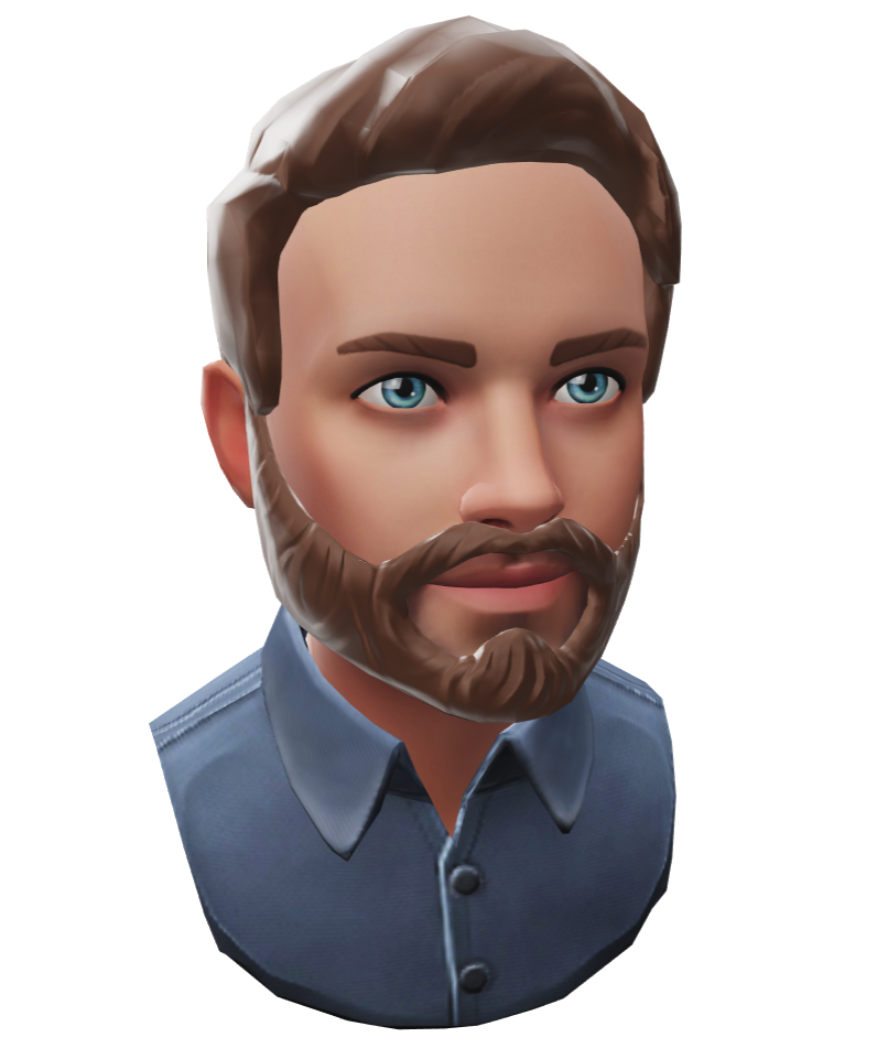
Augmented Reality avatar on a web page

Augmented reality on the web is happening and it’s becoming easier to create! Below you will find a small test of an avatar model I created online and included in this post. The avatar can be viewed in your environment on ARCore and ARKit enabled devices.

ReadyPlayer.me avatar

I used ReadyPlayer.me to create a 3D personal avatar of me. On that website you can use a selfie to create a 3D model that resembles the your image. Afterwards you can make adjustments to its choices. And finally you can download the generated model as a .glb file.
A .glb file is the binary version of a glTF file. glTF is a specification for the efficient transmission and loading of 3D scenes and models by applications.

Google modelviewer

I used Google’s modelviewer to embed the the glb model file in the webpage below and enabled AR viewing.

Here’s the source of the snippet I used:

<script type="module" src="https://unpkg.com/@google/model-viewer/dist/model-viewer.js"></script>
<script nomodule src="https://unpkg.com/@google/model-viewer/dist/model-viewer-legacy.js"></script>
<model-viewer src="avatar.glb" ios-src="avatar.usdz" ar ar-modes="webxr scene-viewer quick-look fallback" ar-scale="auto" alt="Readyplayer.me avatar" auto-rotate camera-controls></model-viewer>

If AR mode is available this button will be visible in the bottom right corner. Depending on which mode is available on your device you will go into AR or open a model viewer.

Here’s the result of running it on an Android phone with ARCore support.

Universal Scene Description

Running the demo on an iPad was a bit more work than I anticipated. Apple only supports the use of models in the .usdz format (Pixar’s Universal Scene Description) As you can see in the modelviewer declaration above there is a separate ios-src for use on iOS devices.

I could not find a simple tool (running on Windows) to convert the .glb to .usdz. There seem to be better solutions on iOS.
I finally found a solution by importing the .glb in Blender, saving a .blend file, importing the .blend file into Unity and finally exporting the model to .usdz.

More

ARCore supported devices; a detailed list of phones & tablets

When you want to use an Augmented Reality app that depends on Google’s ARCore (AKA “Google Play Services for AR”) you will need to know which devices support it. There’s the official list of ARCore supported devices, but that only shows brief names of the supported devices. If you need more details you will have to search for them. Not very efficient with an ever growing list of supported devices especially if you want to find which tablets currently support ARCore apps.

The official list with extra details

There’s a more detailed list available from the Google Play Console, but to be able to download that you will need to have a developer account and upload an app that uses ARCore. Quite a bit of friction if all you are looking for is which hardware you need for ARCore apps to work.

So I decided to bite the bullet and upload a Unity app with ARCore support to my Google Play developer account. I cloned Unity’s arfoundation samples on GitHub, built the app and made an internal release in the Play Store console. After that I was able to access the Device Catalog under Release Management. As you can see below the app was supported by 216 Android devices of a total of 13579 Android devices back in january 2020.

The Download Device List button lets you download a text file (.csv) that also describes details like Form Factor (PC/Phone/Tablet), the System On Chip, Screen Sizes, Screen Densities and more.

The downloaded devicelist.csv can be found on GitHub here.

ARCore supported tablets

A quick filter of the ARCore supported devicelist brings up the tablets that currently support ARCore (September 2020)

  • Acer Chromebook Tab 10
  • LG G Pad 5 10.1 FHD
  • Samsung Galaxy Tab S3
  • Samsung Galaxy Tab S4
  • Samsung Galaxy Tab S5e
  • Samsung Galaxy Tab S6
  • Samsung Galaxy Tab S7
  • Samsung Galaxy Tab Active Pro

The tablets-only devicelist.csv can be found on GitHub here.

Depth API support

In June 2020 Google officially introduced the Depth API. This API allows developers to retrieve a depth map from their phone. Depth maps can be useful for generating occlusions of virtual objects or for scanning your environment. Not all ARCore supported devices support the Depth API. To see which ones do you can add a filter for the devices that are shown in the device catalogue in the Google Play Console.
Add filter, select System Feature, search and select com.google.ar.core.depth

The list of ARCore devices that also support the Depth API can be found on GitHub here.

More

Switched to WordPress

I decided to switch to a WordPress based website to make it easier to manage content and simply make it more modern. I want to add a few of my old VRML projects as YouTube videos.

The glory days of VRML are over. I had a lot of fun with it, but now it’s time to move on.

More