Tagged: shaders

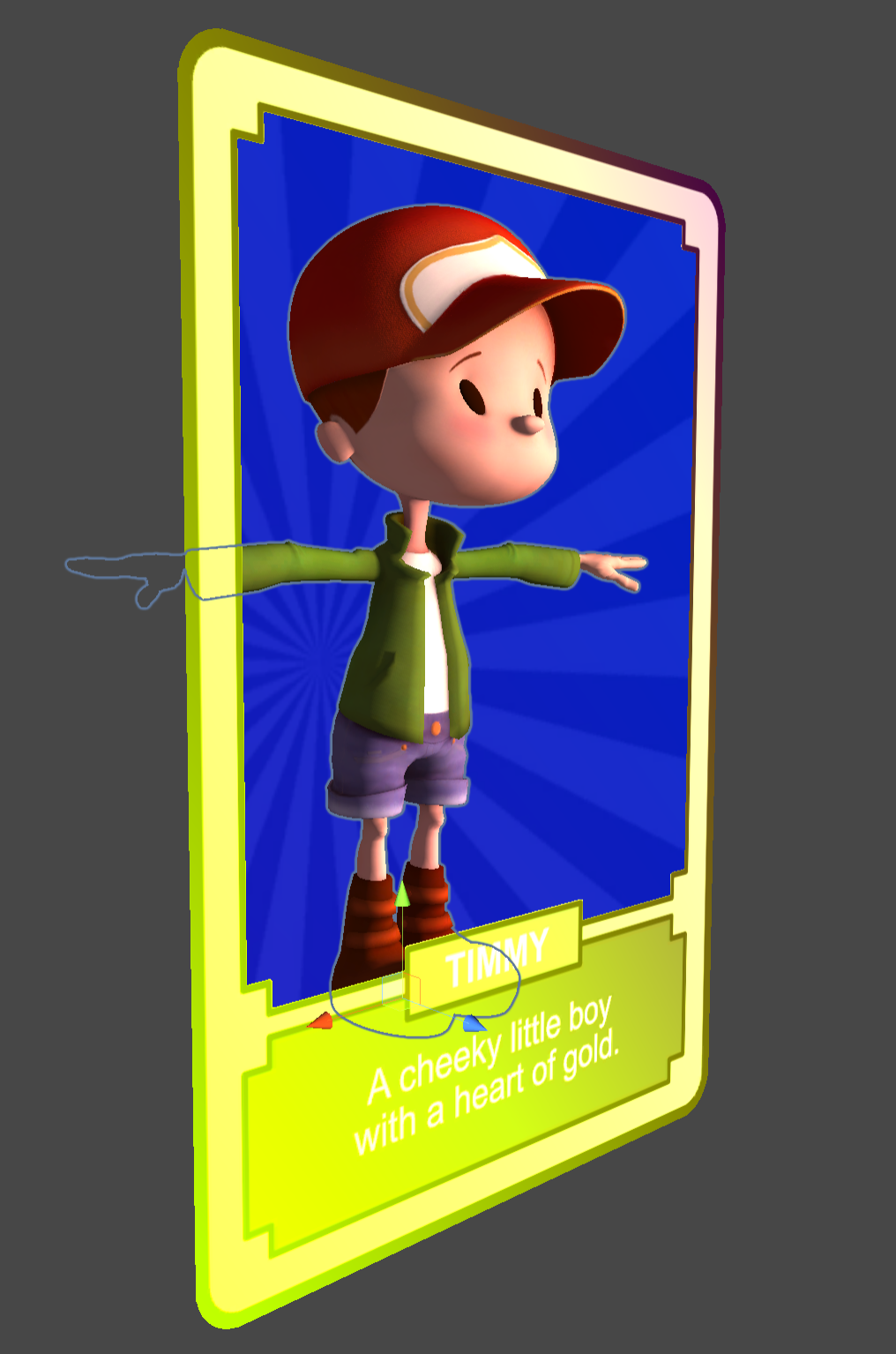
Building a holographic card with the MRTK Standard Shader

Another blog post based on one of the TechArt challenges by Harry Alisavakis. This time the theme was Trading card foil. The challenge was a perfect opportunity to work with the MRTK Standard Shader that is part of the Mixed Reality ToolKit. The MRTK Standard Shader is a shader that is optimized for use in Mixed Reality applications. It is a so called übershader that contains many options that can be enabled when needed. Besides regular lighting it also contains options to add a stencil portal and iridescence.

In this blog post I will go into the three pieces that I used to construct the card shown above:

  • The portal effect that masks out the character and his background
  • The rainbow colors that run across the card and depend on viewing angle (not in the video recording due to a bug)
  • The character pose controlled by viewing angle

The hand interaction is based on the commonly used ObjectManipulator that is part of the MRTK.

Portal Stencil mask

A portal card can easily be achieved with the MRTK Standard Shader when you know what to look for. Here’s the scene setup for the portal card. The top level Card object contains the ObjectManipulator, a BoxCollider, and a NearInteractionGabbable components to make it manipulable on HoloLens.

Without stencil masking the scene looks like the screenshot below. Visible are the PortalBackground, the Timmy character model and FrontSide of the card.

To create a stencil portal the following parts are needed:

Stencil mask producer: The StencilPortal object is a quad that generates a stencil mask. This stencil mask will then be used to determine which pixels should be end up on screen. It is important to note that the stencil mask should be rendered before any object that needs it. Therefore the Render Queue of the StencilPortal material is set to 1999 so it renders before the regular geometry. Furthermore you can see that each rendered pixel of the StencilPortal will fill the mask with values 1 (Read: Always Replace with 1). It is possible to generate different masks with different values. Note that the StencilPortal object is not rendering visible pixels to the screen, but is only used to fill the stencil mask.

Stencil Mask Producer Material

Stencil mask consumer: The PortalBackground and Timmy materials are also using the MRTK Standard Shader, but they have their Stencil setting set to the values below. Basically the shader is told to Keep a pixel when the stencil mask contains a value Equal to 1 and ignore all other pixels of the object.

Stencil Mask Consumer Material

After adjusting the stencil setting this will result in the image below. Note that the FrontSide of the card is disabled in this sceenshot to clearly show the result of the stencil testing.

Stencil Masking Result

With the FrontSide enabled it looks like the image below. The object is a bit bigger than the portal that was rendered so the rounded corners don’t show the stencil masked object behind it. The FrontSide is a backface culled card.

The BackSide object is also a backface culled quad with a different texture, but facing the other side

Iridiscence

Iridiscence is used to generate the varying colors across the surface and view direction. It contains a few variables that you can control. First of all there is a SpectrumMap texture. This is a 1 dimensional lookup texture that will be used as a lookup map for the iridescence color. I used a rainbow color texture, but it could as wel be any other fancy gradient. (See also: Improving the Rainbow) Note that this texture is sampled twice to not only create a color variation based on viewing angle, but also based on UV coordinate. The iridiscence color is added to the albedo (base color) in the fragment shader so this means that iridiscence will be most noticeable on the darkest parts of the material. is Note that the iridescence color is calculated per vertex in the MRTK Standard Shader.

Intensity is a simple scale factor for the amount of iridescence that will be added.
Threshold controls the amount of gradient falloff across the surface, a value of 0 will make it fully viewing angle dependent, a value of 1 will make if fully depend on UV coordinates.
Angle controls the direction of the gradient. A value of 0 will make it the gradient perfectly horizontal, a value -.78 will rotate it 45 degrees left and a value of .78 will rotate the gradient 45 degrees to the right.

To better show how the Iridescene Threshold and Angle influence the final result I created a small test.

MRTK Standard Shader Iridescence Threshold and Angle test setup

Viewing angle dependent character pose

I made the Timmy character inside the card change pose based on viewing angle. This was done by placing a character animation on a timeline that is manually controlled from the PlayableDirector in the character.

Finally here is the PoseByViewAngle script that is used to calculate the animation time based on the viewing angle.

using Microsoft.MixedReality.Toolkit.Utilities;
using UnityEngine;
using UnityEngine.Playables;

public class PoseByViewingAngle : MonoBehaviour
{
    [SerializeField]
    [Tooltip("The PlayableDirector that controls pose")]
    private PlayableDirector PosePlayableDirector;

    [SerializeField]
    private Transform targetTransform;

    private void Start()
    {
        if (!targetTransform)
        {
            targetTransform = CameraCache.Main.transform;
        }
    }

    protected void Update()
    {
        if (!targetTransform)
            return;

        // Get a Vector that points from the target to the main camera.
        Vector3 directionToTarget = targetTransform.position - transform.position;

        var angle = Vector3.Angle(directionToTarget, -transform.forward);

        PosePlayableDirector.time = Map(angle, 0, 90, 1.666f, .333f); 
        PosePlayableDirector.Evaluate();
    }

    public static float Map(float value, float from1, float to1, float from2, float to2)
    {
        return (value - from1) / (to1 - from1) * (to2 - from2) + from2;
    }
}

More

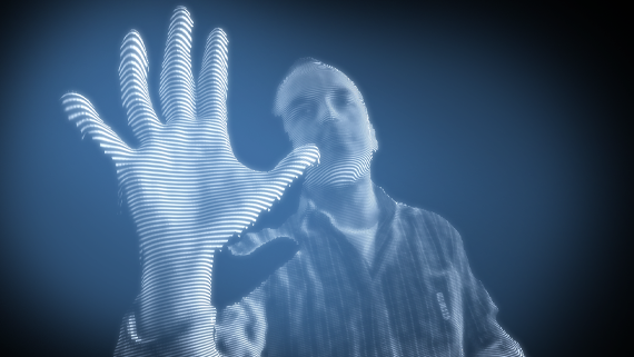
Build your own holographic studio with RoomAlive Toolkit

holoheader

With the current wave of new Augmented Reality devices like Microsoft HoloLens and Meta Glasses the demand for holographic content is rising. Capturing a holographic scene can be done with 3D depth cameras like Microsoft Kinect or the Intel RealSense. When combining multiple 3D cameras a subject can be captured from different sides. One challenge for achieving this is the calibration of  multiple 3D cameras so their recorded geometry can be aligned. In this article I will show you how I used RoomAlive Toolkit to calibrate two Kinects. The resulting calibration is used for rendering a live 3D scene. The source code for this application is available on GitHub.

Calibration with RoomAlive Toolkit

Calibration of multiple Kinects typically requires a manual process of recording a collection of calibration points. With RoomAlive Toolkit it is possible to automatically calibrate multiple projectors and Kinects. Since projectors are used to connect multiple Kinects during calibration a minimum of one projector is required. The only requirement is that the Kinects used can see a fair amount of the projected calibration images. When the calibration is done the projector is no longer needed.

Holographic studio setup

In the picture above you see the geometry and color image that was recorded by two Kinect V2’s. There’s an overlap in the middle. Two magenta frustums indicate where the Kinects were positioned and a purple frustum shows the position of the projector.  Note that both Kinects where placed in portrait mode for better coverage of the room. I placed a few extra items to help the solver algorithm in the RoomAlive Toolkit solve the calibration.

Collecting data from multiple Kinects

Since each Kinect V2 needs to be attached to a separate PC we need a way to collect the depth and color data on the main system. RoomAlive Toolkit also contains a networking solution for doing that. Each system runs a KinectServer WCF service that provides the raw Kinect color and depth data. All data is updated as it arrives without further attempt for synchronization. This results in some artifacts at the seams of the captured scenes.

Rendering live Kinect data

The simplest form of rendering is rendering the raw pieces of geometry of each Kinect. RoomAlive Toolkit contains a SharpDX based example that shows how to do this. It also shows how to filter the depth and how to apply lens distortion correction. Using this information I built a new application based on SharpDX Toolkit (XNA-like layer) to do the rendering. The application contains a few extras so you can tweak a few of the rendering parameters at runtime. I added a clipping cylinder so you can easily reduce the rendered geometry to a single person or object as seen in the video. And just for fun I added a shader to give the live 3D scene a more cliché holographic look. More info about the parameters and controls can be found on the Holographic Studio GitHub page.

Other demos of real time video capture

Holoportation by Microsoft Research
3D Video Capture with Three Kinects by Oliver Kreylos

More