Tagged: Unity

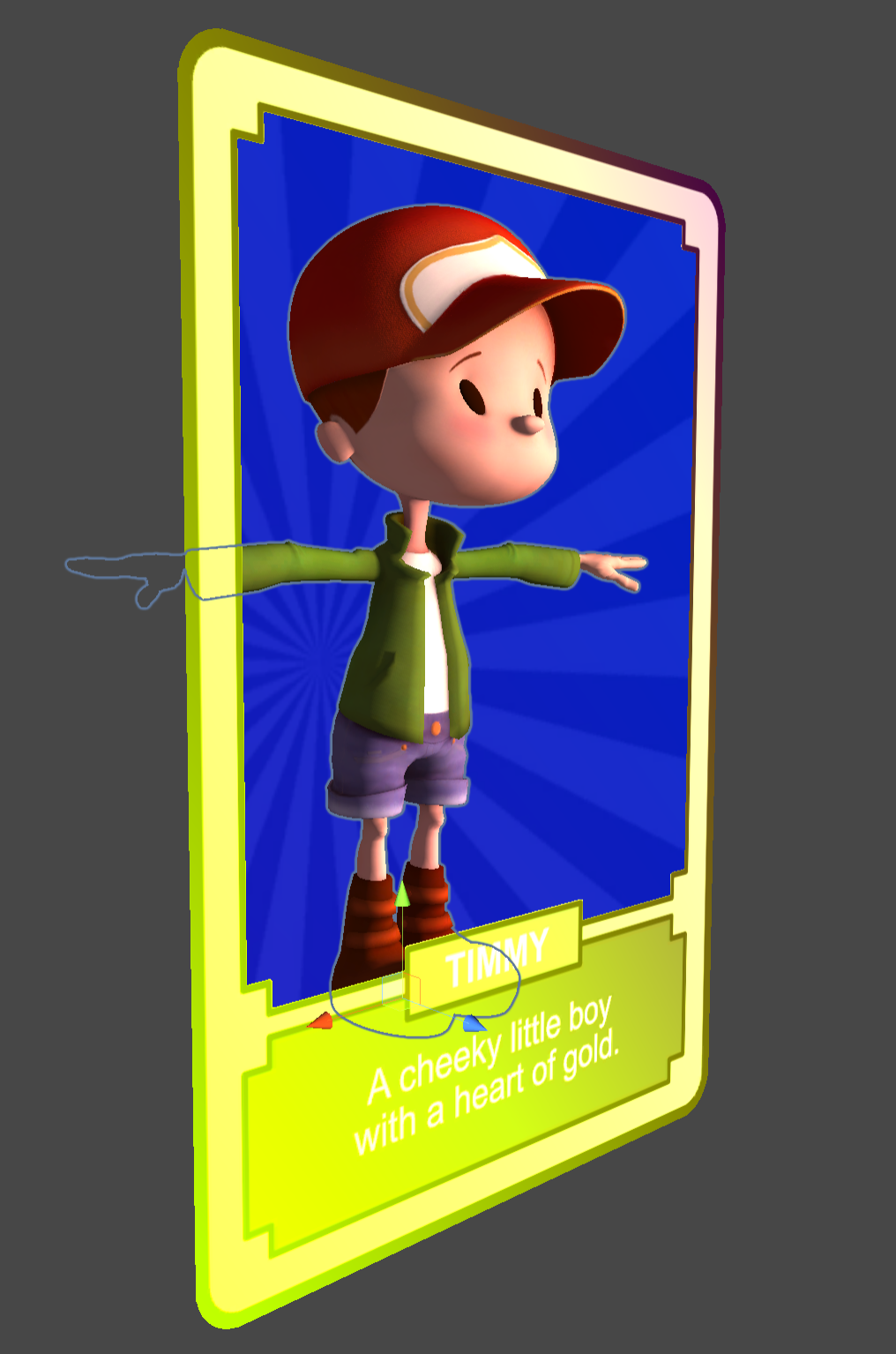
Building a holographic card with the MRTK Standard Shader

Another blog post based on one of the TechArt challenges by Harry Alisavakis. This time the theme was Trading card foil. The challenge was a perfect opportunity to work with the MRTK Standard Shader that is part of the Mixed Reality ToolKit. The MRTK Standard Shader is a shader that is optimized for use in Mixed Reality applications. It is a so called übershader that contains many options that can be enabled when needed. Besides regular lighting it also contains options to add a stencil portal and iridescence.

In this blog post I will go into the three pieces that I used to construct the card shown above:

  • The portal effect that masks out the character and his background
  • The rainbow colors that run across the card and depend on viewing angle (not in the video recording due to a bug)
  • The character pose controlled by viewing angle

The hand interaction is based on the commonly used ObjectManipulator that is part of the MRTK.

Portal Stencil mask

A portal card can easily be achieved with the MRTK Standard Shader when you know what to look for. Here’s the scene setup for the portal card. The top level Card object contains the ObjectManipulator, a BoxCollider, and a NearInteractionGabbable components to make it manipulable on HoloLens.

Without stencil masking the scene looks like the screenshot below. Visible are the PortalBackground, the Timmy character model and FrontSide of the card.

To create a stencil portal the following parts are needed:

Stencil mask producer: The StencilPortal object is a quad that generates a stencil mask. This stencil mask will then be used to determine which pixels should be end up on screen. It is important to note that the stencil mask should be rendered before any object that needs it. Therefore the Render Queue of the StencilPortal material is set to 1999 so it renders before the regular geometry. Furthermore you can see that each rendered pixel of the StencilPortal will fill the mask with values 1 (Read: Always Replace with 1). It is possible to generate different masks with different values. Note that the StencilPortal object is not rendering visible pixels to the screen, but is only used to fill the stencil mask.

Stencil Mask Producer Material

Stencil mask consumer: The PortalBackground and Timmy materials are also using the MRTK Standard Shader, but they have their Stencil setting set to the values below. Basically the shader is told to Keep a pixel when the stencil mask contains a value Equal to 1 and ignore all other pixels of the object.

Stencil Mask Consumer Material

After adjusting the stencil setting this will result in the image below. Note that the FrontSide of the card is disabled in this sceenshot to clearly show the result of the stencil testing.

Stencil Masking Result

With the FrontSide enabled it looks like the image below. The object is a bit bigger than the portal that was rendered so the rounded corners don’t show the stencil masked object behind it. The FrontSide is a backface culled card.

The BackSide object is also a backface culled quad with a different texture, but facing the other side

Iridiscence

Iridiscence is used to generate the varying colors across the surface and view direction. It contains a few variables that you can control. First of all there is a SpectrumMap texture. This is a 1 dimensional lookup texture that will be used as a lookup map for the iridescence color. I used a rainbow color texture, but it could as wel be any other fancy gradient. (See also: Improving the Rainbow) Note that this texture is sampled twice to not only create a color variation based on viewing angle, but also based on UV coordinate. The iridiscence color is added to the albedo (base color) in the fragment shader so this means that iridiscence will be most noticeable on the darkest parts of the material. is Note that the iridescence color is calculated per vertex in the MRTK Standard Shader.

Intensity is a simple scale factor for the amount of iridescence that will be added.
Threshold controls the amount of gradient falloff across the surface, a value of 0 will make it fully viewing angle dependent, a value of 1 will make if fully depend on UV coordinates.
Angle controls the direction of the gradient. A value of 0 will make it the gradient perfectly horizontal, a value -.78 will rotate it 45 degrees left and a value of .78 will rotate the gradient 45 degrees to the right.

To better show how the Iridescene Threshold and Angle influence the final result I created a small test.

MRTK Standard Shader Iridescence Threshold and Angle test setup

Viewing angle dependent character pose

I made the Timmy character inside the card change pose based on viewing angle. This was done by placing a character animation on a timeline that is manually controlled from the PlayableDirector in the character.

Finally here is the PoseByViewAngle script that is used to calculate the animation time based on the viewing angle.

using Microsoft.MixedReality.Toolkit.Utilities;
using UnityEngine;
using UnityEngine.Playables;

public class PoseByViewingAngle : MonoBehaviour
{
    [SerializeField]
    [Tooltip("The PlayableDirector that controls pose")]
    private PlayableDirector PosePlayableDirector;

    [SerializeField]
    private Transform targetTransform;

    private void Start()
    {
        if (!targetTransform)
        {
            targetTransform = CameraCache.Main.transform;
        }
    }

    protected void Update()
    {
        if (!targetTransform)
            return;

        // Get a Vector that points from the target to the main camera.
        Vector3 directionToTarget = targetTransform.position - transform.position;

        var angle = Vector3.Angle(directionToTarget, -transform.forward);

        PosePlayableDirector.time = Map(angle, 0, 90, 1.666f, .333f); 
        PosePlayableDirector.Evaluate();
    }

    public static float Map(float value, float from1, float to1, float from2, float to2)
    {
        return (value - from1) / (to1 - from1) * (to2 - from2) + from2;
    }
}

More

Blowing bubbles with Shader Graph

I ran into a two weekly Techart challenge by Harry Alisavakis with the theme Watercolors. I decided to participate and use Shader Graph in Unity for doing some soap bubble rendering.

Reflections & Iridescence

Real life soap bubble

The most visible features of a soap bubble are its reflections and its rainbow like colours. You can see reflections from both the front and back side of the bubble surface. This results in a mirrored reflection of the environment of the bubble.

The colours are caused by interference of the light that is reflected from the outside and the inside of the thin bubble surface. This phenomenon is called iridescence and it can also be found in sea shells, butterflies, insects, but you may also know it from the surface of a CD. When you inspect the bubble surface closely you can see a complex pattern of dancing colours. This is caused by variations in the bubble surface thickness due to complex fluid interactions that are known as the Marangoni effect.

Reflections in Shader Graph

For the reflections I created a simple room with with two fake windows. A reflection probe was used to bake it into a cubemap. Alternatively you could also use a HDRI image captured in real-life.

Bubbles need windows to reflect

A basic PBR graph with the Workflow set to Specular, Surface to Transparent and a Smoothness of 1 will already give you a nice reflective material. Add in a bit of Fresnel effect so the reflections are mostly noticeable on the outside and here’s the result.

Shaders are made easy with Shader Graph
Cubemap reflection with Fresnel falloff

Iridescence in Shader Graph

I took a more artistic approach for the simulation of the bubble surface variations by blending two layers of scrolling noise. This misses the swirls that you typically see in a real bubbles, but this won’t be noticeable at a distance. I added a vertical falloff to simulate that the thickness of a bubble is a bit larger at the bottom of the bubble. The surface thickness variations result an animated grayscale value. A gradient lookup gradient is then used to determine the iridescence colour. The gradient is based on a paper by Andrew Glassner.

The iridescence part hooks into the specular colour of the PBR node
Front face reflection and iridescence

Double sided materials

To create a double-sided material with different handling of forward and backward facing materials you can use the IsFrontFace node and branch into different parts of the shader based on the value. This works well with opaque materials and can be done in a single pass. Below you see a simple example that displays the result on an open cylinder.

Opaque material marked as a Two Sided
Two-sided opaque material ShaderGraph
Open cylinder with two-sided material applied

Double sided transparency

With transparent materials we typically want to do a separate backface pass and frontface pass to at least have a coarse way of sorting the model surfaces. That is easy to do in a ShaderLab (hand-coded) shader, but a bit harder when using Shader Graph.
Since the Universal Rendering Pipeline (URP) only supports one pass materials by default we need to come up with a different trick. We could create a copy of the mesh and render that with a separate material for the backside, but that would mess up the scene tree. And it would even become worse if the geometry were dynamic. Instead I chose to add a second material that uses the same Shader Graph shader but with a RenderFront flag to enable the front or backface rendering.
Note that Unity shows a warning and advises the use of multiple shader passes, which are not supported when using URP. 🤷‍♂️

Two-pass mesh rendering with different materials

The Shader Graph is using the RenderFront flag combined with the IsFrontFace node to determine if the front or backface needs to be rendered. I used AlphaClipping the prevent rendering of the backface when frontface rendering is active. Note that for backface rendering the surface normal needs to be flipped.

Two-sided reflections part
Bubble with two sided reflection and iridiscence

More

Augmented Reality avatar on a web page

Augmented reality on the web is happening and it’s becoming easier to create! Below you will find a small test of an avatar model I created online and included in this post. The avatar can be viewed in your environment on ARCore and ARKit enabled devices.

ReadyPlayer.me avatar

I used ReadyPlayer.me to create a 3D personal avatar of me. On that website you can use a selfie to create a 3D model that resembles the your image. Afterwards you can make adjustments to its choices. And finally you can download the generated model as a .glb file.
A .glb file is the binary version of a glTF file. glTF is a specification for the efficient transmission and loading of 3D scenes and models by applications.

Google modelviewer

I used Google’s modelviewer to embed the the glb model file in the webpage below and enabled AR viewing.

Here’s the source of the snippet I used:

<script type="module" src="https://unpkg.com/@google/model-viewer/dist/model-viewer.js"></script>
<script nomodule src="https://unpkg.com/@google/model-viewer/dist/model-viewer-legacy.js"></script>
<model-viewer src="avatar.glb" ios-src="avatar.usdz" ar ar-modes="webxr scene-viewer quick-look fallback" ar-scale="auto" alt="Readyplayer.me avatar" auto-rotate camera-controls></model-viewer>

If AR mode is available this button will be visible in the bottom right corner. Depending on which mode is available on your device you will go into AR or open a model viewer.

Here’s the result of running it on an Android phone with ARCore support.

Universal Scene Description

Running the demo on an iPad was a bit more work than I anticipated. Apple only supports the use of models in the .usdz format (Pixar’s Universal Scene Description) As you can see in the modelviewer declaration above there is a separate ios-src for use on iOS devices.

I could not find a simple tool (running on Windows) to convert the .glb to .usdz. There seem to be better solutions on iOS.
I finally found a solution by importing the .glb in Blender, saving a .blend file, importing the .blend file into Unity and finally exporting the model to .usdz.

More

ARCore supported devices; a detailed list of phones & tablets

When you want to use an Augmented Reality app that depends on Google’s ARCore (AKA “Google Play Services for AR”) you will need to know which devices support it. There’s the official list of ARCore supported devices, but that only shows brief names of the supported devices. If you need more details you will have to search for them. Not very efficient with an ever growing list of supported devices especially if you want to find which tablets currently support ARCore apps.

The official list with extra details

There’s a more detailed list available from the Google Play Console, but to be able to download that you will need to have a developer account and upload an app that uses ARCore. Quite a bit of friction if all you are looking for is which hardware you need for ARCore apps to work.

So I decided to bite the bullet and upload a Unity app with ARCore support to my Google Play developer account. I cloned Unity’s arfoundation samples on GitHub, built the app and made an internal release in the Play Store console. After that I was able to access the Device Catalog under Release Management. As you can see below the app was supported by 216 Android devices of a total of 13579 Android devices back in january 2020.

The Download Device List button lets you download a text file (.csv) that also describes details like Form Factor (PC/Phone/Tablet), the System On Chip, Screen Sizes, Screen Densities and more.

The downloaded devicelist.csv can be found on GitHub here.

ARCore supported tablets

A quick filter of the ARCore supported devicelist brings up the tablets that currently support ARCore (September 2020)

  • Acer Chromebook Tab 10
  • LG G Pad 5 10.1 FHD
  • Samsung Galaxy Tab S3
  • Samsung Galaxy Tab S4
  • Samsung Galaxy Tab S5e
  • Samsung Galaxy Tab S6
  • Samsung Galaxy Tab S7
  • Samsung Galaxy Tab Active Pro

The tablets-only devicelist.csv can be found on GitHub here.

Depth API support

In June 2020 Google officially introduced the Depth API. This API allows developers to retrieve a depth map from their phone. Depth maps can be useful for generating occlusions of virtual objects or for scanning your environment. Not all ARCore supported devices support the Depth API. To see which ones do you can add a filter for the devices that are shown in the device catalogue in the Google Play Console.
Add filter, select System Feature, search and select com.google.ar.core.depth

The list of ARCore devices that also support the Depth API can be found on GitHub here.

More

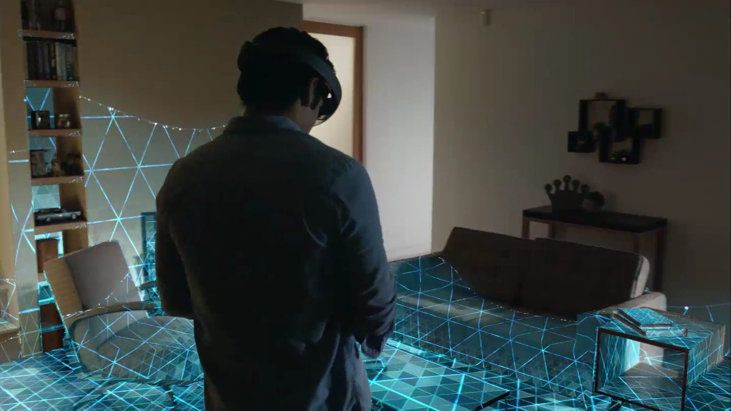
HoloLens scanning effect in Unity

In a previous blog post I talked about my attempt to rebuild the HoloLens scanning effect as shown in this video. After following the HoloLens Academy tutorials I decided to see how easy my existing shader could be integrated in Unity. It turned out that only a minimal amount of plumbing was needed.

HoloLens room scan

I took the project files from the HoloLens course on spatial mapping (Holograms 230). That course explains how you can apply your own material and a custom shader to the mesh that is generated by the spatial mapper. For quick iterations you can even load a previously saved room mesh. I added a new unlit shader and a material using it. This material is used by the Spatial Mapping Manager script to apply to the mesh coming from the spatial mapper.

Unity shader variables

Most of the plumbing came down to defining variables and using them in the shader. The main animation is driven by the global time. Unity provides this as a built-in variable vector _Time, where the y-component contains the elapsed time in seconds. I added a few variables to control the looks and behavior of the effect like Main Color, Speed, Triangles Scale and Range Scale.

The center of the effect is also a variable that can be configured. It could be updated by using doing a Raycast intersection as explained in the HoloLens Academy tutorials. Currently the effect keeps pulsating every 5 seconds. To only trigger the effect on an event the used global time could be replaced by a separately controlled progress variable.

Differences with original effect

To create the effect of triangles walking across the floor and up the walls the shader needs to calculate uv coordinates based on a world location. Preferably with as little seams as possible. I used the horizontal distance to the configured center point and added the vertical distance instead of using the direct distance to the center point. This works reasonably well on connected surfaces, but note that it is not a real walk across the topology of the mesh.

The effect in the original video has a slightly different border effect that has some more distortions and a different color. I experimented with mimicking that effect, but decided to leave that out. I used the effect in an interactive installation where I preferred a stronger border that looked like a wave was expanding outwards.

The source code of the project is available on Github.

HoloLens Shader Pack

A new version of this shader was optimized for running on the actual HoloLens device. This shader and many others are available in the HoloLens Shader Pack that is available on the Unity Asset Store.
More